Shear (4) – back to the basics
- Si Shen

- Oct 3, 2020
- 2 min read
The fundamentals of shear
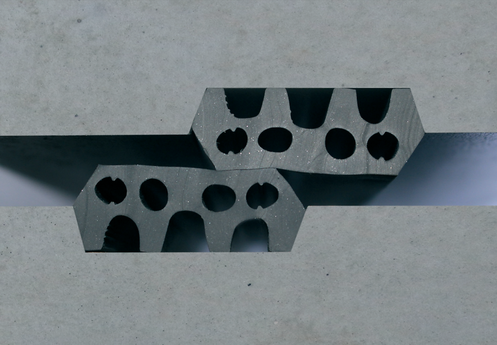
Shear can be understood as the sliding action between adjoining parts of a structural element. A few standing-alone blocks have little sliding resistance between them. Any block will tend to fall if nothing is holding it up. However, if I compress them with my fingers to generate higher friction between them, I effectively create higher shear capacity. As you can see shear capacity between the blocks along is able to hold up the middle block. The same principle applies at both macro and micro scale – whether it is between two visible parts, or between particles.

Shear goes hand-in-hand with bending. Bending relies on shear. No shear no bending. Shear resistance creates bending resistance. Shear force is the rate of change of bending moment – see later in this blog. A beam is able to span across a length because shear converts the loading on it into internal stresses in a beam. It helps the loading find its resistance and be neutralised.
Shear capacity makes a material stiff. Typically, the more shear capacity there is, the stiffer a material is. Fluid has little shear between particles hence no bending resistance. Zero shear capacity is actually a reasonably accurate definition of fluid. In geotechnical engineering, there is ‘plasticity index’ for soil, which basically means how ‘watery’ the soil is. The more watery the soil is, the lower the plasticity index, and the lower friction resistance it has, and hence the lower shear capacity it has.
First principles of drawing bending and shear diagrams:
1. Shear helps a loading find its resistance and be neutralised. A shear force diagram shows the accumulation of loading towards the supports of a member. Therefore shear diagrams always show:
· A step at the location of a point load, because it gets a step change in accumulation.
· A constant slope along a member subject to uniformly distributed loads, because the accumulation is steady
· No change in value if no more loadings to be accumulated before reaching supports
2. Shear force is the rate of change of the bending moment.
· Where shear force is zero – bending moment is a horizontal (constant) straight line
· Where shear force is constant – bending moment is on a constant slope
· Where shear force is on a constant slope – bending moment is on a parabolic curve
Other tips:
· Drawing the deflected shape may be helpful in understanding the structural behaviour. For the majority of the time, it is more intuitive to draw the deflected shape first, from which points of contraflexure (points where bending turns from one direction into the opposite) can be found. At these points of contraflexure, bending moments are always zero.
· Pin joints/supports give no disruption to the shear force, but resets moment to zero, because the structure is free to rotate at these points.
· Under a point load, shear diagram always shows a step, which may take the form of a rectangular block, whereas bending moment diagram always shows an inclined straight line.
· Under a distributed load, shear diagram always shows an inclined straight line and bending moment diagram always shows a parabolic curve. The ‘belly’ of the curve locates somewhere in the span whereas at the supports the diagram is always pointy.


Comments